
How To Efficiently Speed Up Mesh Generation | PLAXIS Blog
June 15th, 2021
PLAXIS 3D is a very powerful tool that can provide extremely valuable information to geotechnical engineers, but did you know there are some insider tips that can help you save time? Here is some useful information on how to efficiently use PLAXIS 3D to confidently move forward in creating complex 3D mesh and optimally and successfully perform analyses.
Understanding the PLAXIS modeling and meshing workflow
PLAXIS 3D uniquely addresses geometry creation in a very particular and unique way as it offers two independent geometry definition environments:
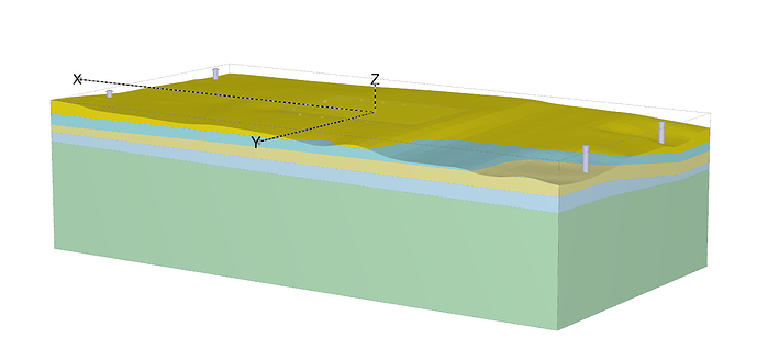
- One for soil (Soil geometry mode): Representing soil stratigraphy before project construction starts (see Figure 1a)
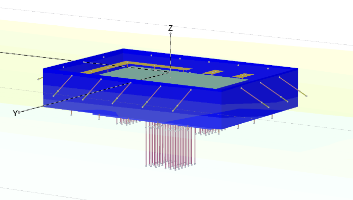
- One for structures (Structure geometry mode): Displaying all project-related geometry (see Figure 1b)
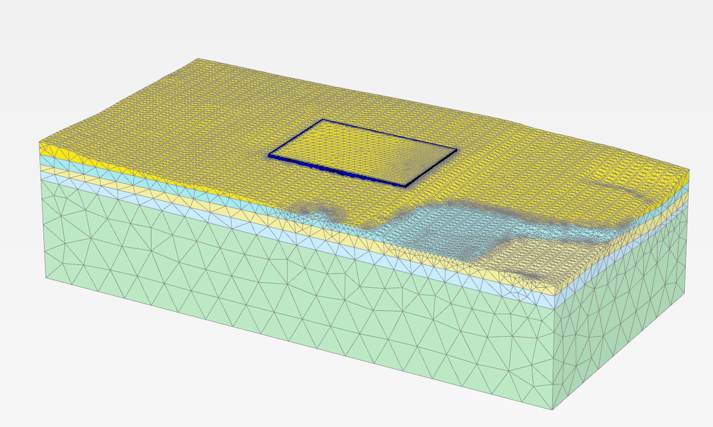
From a geometry definition point of view, this is very convenient. You don’t have to worry about geometry connectivity among any geometrical components placed in the model. The PLAXIS 3D geometry kernel engine automatically takes care of performing intersection and re-clustering (i.e., eliminating overlapping objects) of all constitutive geometrical components (see Figure 1c).

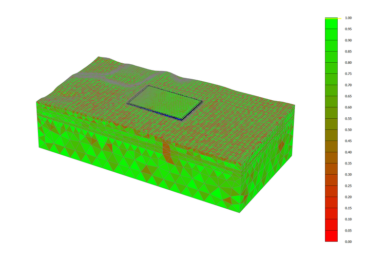
The finite element mesh is generated based on the “clustered” geometry (as displayed in Figure 1c). The generation of the finite element mesh is a highly automated process in PLAXIS only requiring a very limited amount of user interaction. Only unstructured meshes are generated in PLAXIS, in which you can control the “average” element size (either globally or locally). Such meshes are composed of quadratic tetrahedra elements in 3D and either 4-th order or quadratic triangular elements in 2D. Additional considerations are accounted for by the PLAXIS mesher to determine a satisfactory element shape, which is important for obtaining accurate numerical results. This might provide additional mesh refinement locally and sometimes significantly impact mesh generation time.
The finite element mesh is generated based on the “clustered” geometry (as displayed in Figure 1c). The generation of the finite element mesh is a highly automated process in PLAXIS only requiring a very limited amount of user interaction. Only unstructured meshes are generated in PLAXIS, in which you can control the “average” element size (either globally or locally). Such meshes are composed of quadratic tetrahedra elements in 3D and either 4-th order or quadratic triangular elements in 2D. Additional considerations are accounted for by the PLAXIS mesher to determine a satisfactory element shape, which is important for obtaining accurate numerical results. This might provide additional mesh refinement locally and sometimes significantly impact mesh generation time.
Some good habits
The quick generation of an optimized mesh always starts with some simple considerations, which we would like to summarize here.
Only model what is necessary
The first tip is to model and mesh only what is necessary and relevant for your design. For instance, always start identifying symmetry conditions and make use of then. This could be plane symmetry for excavation, cyclic symmetry for quay wall, etc.
Please take special care to note the introduction of any small details. The presence of any geometry object whose dimensions are less than 1/100 of the overall model dimension should indicate that perhaps the model dimensions are too large, or that the extremely small object might not need to be considered (see Figure 3).
Is CAD import always the best option?
At first, importing the geometry from a CAD model often appears to be an interesting option. Novice PLAXIS 3D users usually find themselves much more proficient at creating a geometry in a modeling environment they are already familiar with, or simply (and this is the most common case) because the CAD model already exists!
However, there are a few things users might not be aware of when importing CAD geometry in PLAXIS 3D:
- The CAD model might contain a significant quantity of irrelevant objects (construction lines, dimensions, annotations, large amount of insignificant details, etc. ) that would need to first be properly identified in the PLAXIS modeling environment and then deleted.
- CAD geometries are meant be used for drawing, drafting reports, or calculating quantities …. not being meshed. Meshing requires a much higher level of accuracy and contiguity of the geometry definition. For this reason, any imported CAD geometries must systematically undergo a thoughtful diagnosis with any possible associated repairing operations before being tentatively considered and meshed. Any remaining imprecisions in the geometry will surely lead to either intersection or meshing issues.
Because of this, we highly recommend the use of CAD import only for geometries that simply cannot be created natively in PLAXIS 3D or that would require excessive re-modeling time. In many cases, it is much easier and significantly faster to recreate the geometry natively from scratch rather than trying to import it from a CAD package.
Pushing the boundaries
As previously stated, PLAXIS 3D is an extremely powerful tool that enables you to create simple geotechnical models quite quickly once you become familiar with the modeling environment and workflow. It is important to follow the proper methodology to save time when creating more complex geometry and associated meshes.
Automation and scripting
Complex models often contain a significant number of objects. Using automation technology can be enormously helpful by helping you avoid errors and save time.
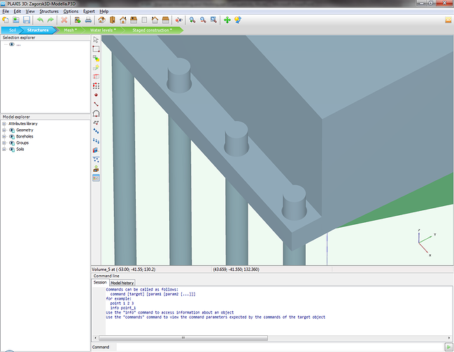
PLAXIS offers a simple command-line mechanism that is easy to access. The tool reads a command file to help you generate a model. Note that such a command history is systematically generated during any model creation in PLAXIS, offering even greater accessibility of the technology (see Figure 5). In combination with a Microsoft Excel spreadsheet, where formulas can be used and corresponding PLAXIS commands written, this has proven to be a very efficient means to speed up and reduce the number of possible errors and inconsistencies in geometry definition.

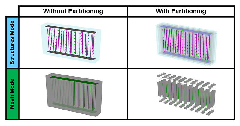
Partitioning
A complex geometry can always be subdivided into a set of simpler topological shapes. This is basically what lies behind the word “partitioning.” This process requires the definition of additional geometry objects (mostly “slicing” surfaces) for the purpose of introducing additional but simpler geometrical objects to the mesher and therefore reducing the number of “topological” constraints. (see Figure 6). This technique has proven to:
- Systematically result in successful meshing
- Significantly reduce mesh generation time especially when EMR (enhanced mesh refinement) option is not selected
- Offer more control over mesh density in the model itself
Partitioning is not mandatory. It does not bring additional value to standard or relatively simple geotechnical models. However, partitioning has proven to be useful for complex geometry and lengthy meshing processes, leading to a considerably less dense and more affordable mesh compared to models with no partitioning.
Blog author: Richard Witasse, Principal Product Manager, Geotechnical