Wilde Analysis Ltd

engineering by analysis

  • Simulation Home
  • Capabilities
    • Design Simulation
      • Structural Analysis (FEA)
      • Fluid Dynamics (CFD)
      • Computational Electromagnetics (CEM)
      • Thermal Management
      • Design Code Assessment
      • Design for Reliability
      • All Design Simulation
    • Manufacturing Process Simulation
      • Metalforming, Machining & Heat Treatment
      • Plastic Injection Moulding
      • Plastic Packaging & Extrusion
      • Additive Manufacturing & 3D Printing
      • Process Optimisation
      • Asset Performance Management
      • All Manufacturing Process Simulation
    • Built Environment Simulation
      • Wind Engineering
      • Daylight, Sunlight & Right to Light
      • Geotechnical & Structural Analysis
      • Heating, Ventilation & Air Conditioning (HVAC)
      • Cleanroom & Hygienic Zone Design
      • Data Centre Cooling
      • All Building Physics
  • Industries
    • Aerospace & Defence
    • Industrial Equipment
    • Oil & Gas
    • Automotive & Off-Road
    • Marine & Subsea
    • Plastics, Composites & Rubber
    • Built Environment
    • Medical & Healthcare
    • Rail
    • Chemical & Process
    • Metals
    • Renewable Energy
    • Consumer Products
    • Nuclear
    • University & Research
    • Electronics & Electrical
    • All Industries
  • Software
    • Ansys – Mechanical & Fluids
      • 3D Design
      • Structures
      • Fluid Dynamics
      • Multiphysics
    • ANSYS – Electronics
      • Electromagnetics (LF)
      • Electromagnetics (HF)
      • Signal & Power Integrity
      • Electronics Cooling
    • Manufacturing Process Software
      • Moldex3D — Plastic Injection Moulding
      • DEFORM – Bulk Metalforming & Heat Treatment
      • Ansys Additive — Topology & 3D Printing
      • Flownex — 1D Fluid Systems
    • Ansys – Platform
      • Materials
      • Cloud & Elastic Licensing
      • Startup Programme
    • Ansys – Systems
      • Functional Safety
      • All Products
    • Bentley Systems
      • PLAXIS — Geotechnical Analysis
      • gINT — Geotechnical Data Management
      • Buy Online Here
  • Consulting
    • Capabilities
      • Design Simulation (FEA, CFD & CEM)
      • Manufacturing Process Simulation
      • Built Environment Simulation
      • Safety & Reliability Analysis
      • Design, Materials & Testing
    • Services
      • Project Options
      • Staffing & Secondments
      • Gap Analysis
      • Technology Transfer
      • Technical Support
    • Assurance
      • Experience
      • Certifications & Associations
      • Software Tools
      • Quality & Environmental Management
      • Cyber Security & Data Protection
  • Training
    • Online Courses
      • Simulation Theory & Best Practice
      • Ansys
      • DEFORM
      • Moldex3D
      • Safety & Reliability
    • Classroom Courses
      • Simulation Theory & Best Practice
      • Ansys
      • DEFORM
      • Moldex3D
      • Safety & Reliability
    • On Request Training
      • PLAXIS
      • Design By Analysis
      • Design for Electromagnetic Compatibility (EMC)
      • Safety & Reliability
  • Support
  • Resources
  • About
    • Our Company
      • Senior Management
      • History
      • Careers
      • Legal Notices
      • WildeRisk.co.uk
    • Assurance
      • Experience
      • Certifications & Associations
      • Quality & Environmental Management
      • Cyber Security & Data Protection
      • Privacy Policy
    • What’s On
      • Training & Events Calendar
      • Webinars, Seminars, Conferences & Exhibitions
      • News
      • Blogs
      • Community Support
  • FREE TRIALS
  • Contact
  • LinkedIn
  • Twitter
  • Facebook
  • YouTube
  • Blog
  • +44 (0) 161 474 6886
  • LinkedIn
  • Twitter
  • Facebook
  • YouTube
  • Blog
  • +44 (0) 161 474 6886

Flownex

Home » Engineering Simulation & Risk Management Software » Manufacturing Process Simulation Software » Flownex

loading...

Flownex Simulation Environment (SE) is a fast, reliable and accurate total system and subsystem solution to thermal-fluid simulation, enabling you to rapidly predict, design and optimise for flow rates, pressures, temperatures and heat transfer rates.

Flownex
  • Contact Us for a Demo
  • Overview
  • Software Options
  • Applications
  • What's New in Release 2019?

Developed by M-Tech Industrial, Flownex provides an ideal systems-based simulation tool for virtually all fluids-based processes. 
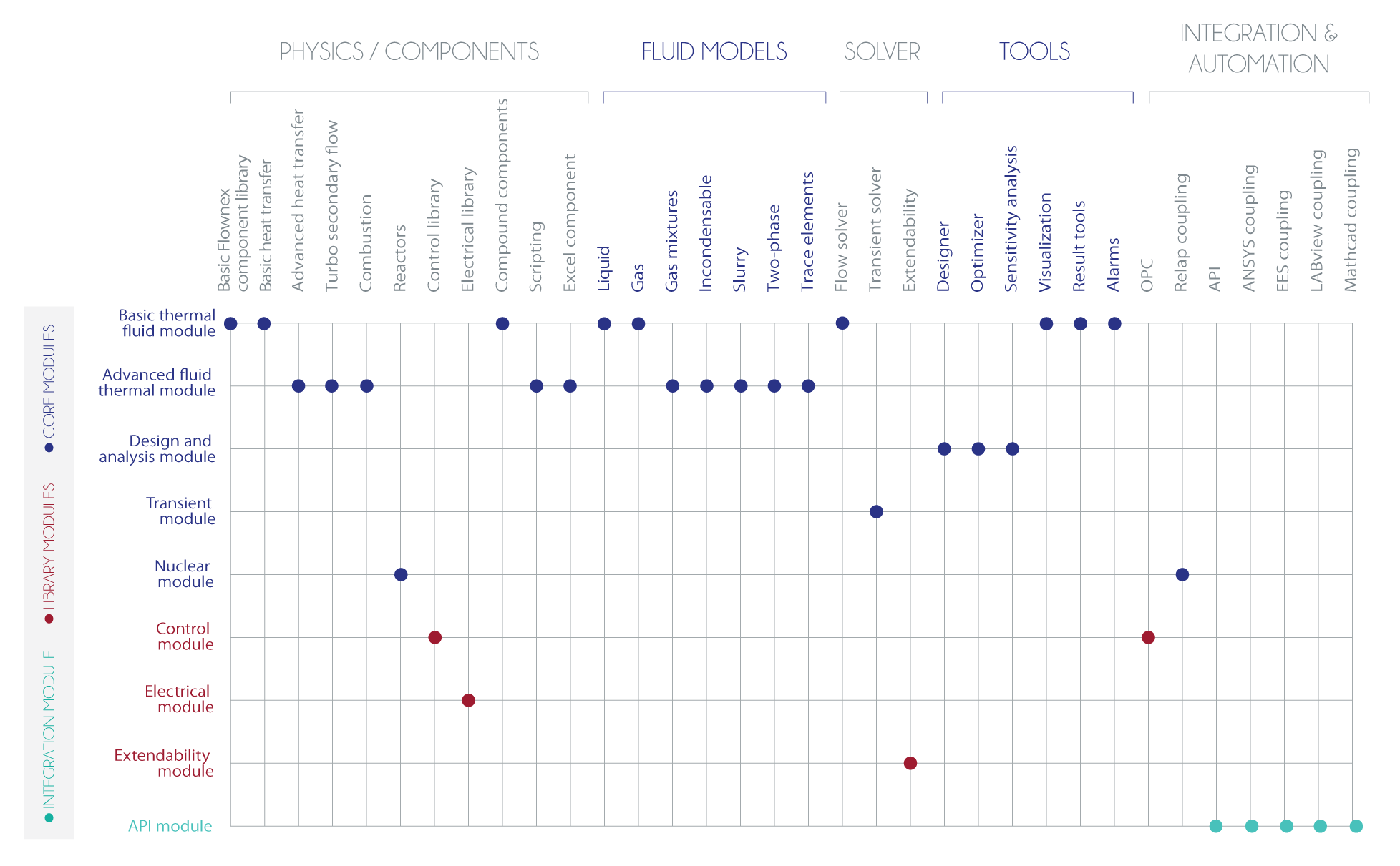
It can model any combination of liquid, gas, two phase, slurry and mixture flows in both steady state and dynamic conditions, coupled with a comprehensive library of components including pumps, turbines, valves, compressors and heat exchangers.

Flownex Simulation Environment can be configured to your requirements from a series of modules.

Flownex software options matrix


Rapid Design Of Small Modular Nuclear Reactors (SMRs) >>

Flownex within Mining Industry >>

Robust Slurry System Design  >>

Rapid Analysis & Design of Cooling Flow Paths for Turbomachinery Turbine Combustion Chamber Analysis & Design Calculating Pipe Bend Forces

Rapid Analysis & Design of Cooling Flow Paths for Turbomachinery >>

Turbine Combustion Chamber Analysis & Design >>

Calculating Pipe Bend Forces >>

Rapid Design Of Small Modular Nuclear Reactors (SMRs) Flownex within Mining Industry Robust Slurry System Design

Further Flownex Application Examples >>

Adaptive Timestep

An adaptive timestep functionality has been added to the Flownex solver that automatically refines the timestep size through a transient simulation. This results in small timesteps when fast transients (such as pressure pulses during water hammer) are occurring to accurately predict the solution and larger timesteps when possible to affect shorter solving times.

This feature monitors the pressure, energy, mass flow and density of all the components and will automatically reduce the timestep to ensure that the solution remains within the specified accuracy criteria. This allows the user to accurately predict fast transients such as pressure pulses without having to perform a temporal convergence study first.

For more information about how the adaptive timestep algorithm is implemented, please refer to the Scheduling chapter of the General User Manual. 

A button has been added to the toolbar that gives the user quick access to the time step settings. It is located next to the Reset Time button in the Simulation Control section.

Cavity Editor

The inputs of the Rotor-Rotor and Rotor-Stator components have been significantly enhanced in order to allow a user to easily specify a complex geometry for the cavity.

The complex geometry can be specified by using the Cavity Editor, which opens when double clicking on a Rotor-Rotor or Rotor-Stator component. The Cavity Editor allows the user to import a background picture for the cavity. The geometry and dimensions can then be defined in the picture in the Cavity Editor.

After a picture has been imported, the user can define the dimensions of the cavity by specifying two points at any location on the drawing. Thereafter, the rotor and stator surface geometries are easily drawn on top of the picture.

Other geometric items like the position of bolts, gap and shroud width, as well as defining the discretization is also done easily using this Cavity Editor.

Gibbs Free Energy Reactor

The combustion category has been renamed to Chemical Reactions. The existing Adiabatic Flame model is a chemical reaction where the end temperature and composition of the end product of the reaction is determined by the CEA calculations. Another component has been added to the Chemical Reactions library where the user can specify the end temperature of the chemical reaction, namely the Gibbs Free Energy Reactor.

Script Debugging

The Scripts can be debugged if a debugger is installed on the computer. Visual Studio is recommended for debugging. The Debug button is located on the Script editor. After clicking the Debug button then the user will be prompted to select which debugger to use. A breakpoint can be placed in the relevant function requiring debugging and the run button can be pressed in the debugger to continue. The debugger will break as soon as your chosen line of code is hit.

The component uses the NASA CEA program to predict the reaction products at the specified end temperature. This component will then calculate the change in Gibbs free energy and enthalpy during the reaction. As part of this enhancement, a Gibbs free energy result has been added on all flow nodes. The first application of this reactor is to model fuel cells and use Flownex to optimise the surrounding systems. There are however many other possible applications.

Heat Exchanger Improvements

The Heat Exchanger components in Flownex has been updated. These components are now easier to use and a few essential features have been added. The heat exchangers that has been updated is the Shell and Tube Heat Exchanger, Finned Tube Heat Exchanger and the Recuperator, which has been renamed to a Plate Heat Exchanger. The changes make using the heat exchangers for a general application like radiators etc. simpler.

Furthermore, fouling factors and fin efficiencies have been added to the heat exchangers where relevant. These can be used to model degradation over time and changes in the condition of the heat exchangers.

1. Shell and Tube Heat Exchanger
2. Finned Tube Heat Exchanger
3. Plate Heat Exchanger

Finned Tube Heat Exchanger

New icons have been added for the Finned Tube heat exchanger and the names now clearly indicate the fin side and the tube side.

A simplified set of inputs has been added to specify the geometry of a rectangular finned tube heat exchanger with round fins. This is the default option now.

The user now specifies more readily available geometric parameters like the heat exchanger width height and length as well as tube and fin diameters. The older more generic specification is still available.

The fin side supports specification of the friction factor through a constant value, using a script or using a Fanning friction factor chart. By default, the Fanning friction chart is used. The user can however easily use a correlation from another source in the script defined friction factor specification.

The shell side now supports script defined heat transfer coefficient calculation, constant value specification and Stanton Prandtl charts. By default, Stanton Prandtl chart is used. The user can however easily use a correlation from another source in the script defined heat transfer coefficient calculation.

The tube side supports specification of the friction factor through a constant value, Darcy Weisbach correlations, using a script or using a Fanning friction factor chart. By default, the Darcy Weisbach correlation is used.

The tube side supports built-in correlations for the heat transfer coefficient calculation, as well as script defined heat transfer coefficient calculation, constant value specification and Stanton Prandtl charts. By default, the Gnielinski correlation is used for the tube side heat transfer coefficient calculation.

Plate Heat Exchanger

The Recuperator heat exchanger has been renamed to the Plate Heat Exchanger, which describes the functionality of the heat exchanger better. New icons have been added for this heat exchanger too.

Both sides support specification of the friction factor through a constant value, Darcy Weisbach correlations, using a script or using a Fanning friction factor chart. By default, the Darcy Weisbach correlation is used with the addition of friction factor multipliers that can be used in the laminar and turbulent ranges to adjust the friction factor.

Both sides support built in correlations for the heat transfer coefficient calculation, as well as script defined heat transfer coefficient calculation, constant value specification and Stanton Prandtl charts. By default, the Gnielinski correlation is used for the tube side heat transfer coefficient calculation.

Graph Improvement

The graphs inputs have been modified such that only basic graph properties are shown when creating a new graph to ease formatting/styling. Additional formatting properties are available when checking the Advanced Formatting properties.

To learn more about how Flownex software can help you or arrange an upgrade, please submit your request below:


    Enquiry:

    • Flownex Training
    • Flownex Resources

    Selected Resources

    • » Brochure: Flownex 1D Thermo-Fluid Simulation

    • » Brochure: Flownex Customer Stories

    • » Brochure: Flownex for Turbomachinery

    • » Brochure: Flownex Modules

    • » Brochure: Flownex Release

    View more resources »

    Client Feedback

    Prev

    I was very impressed with the knowledge and tools available to us through Wilde and the accuracy of their first model predictions compared to my test results. This has already become a seminal piece of work that will underpin a significant future product development.

    Edbro
    Next

    Case Studies

    • » Optimising Oil Flow in Telescopic Cylinders by 1D Network & 3D CFD Analysis

    • Events

      • » Shrinkage Compensation and Reverse Warp in Moldex3D | Moldex3D Webinar
      • » Ansys CFD Solutions for Aviation Engine Gear Systems | Ansys Webinar
      • » Turbo in 15 Minutes: Improving Durability with Aeromechanics | Ansys Webinar
      • » Simulation World | Ansys Seminar
      • » Turbo in 15 Minutes: Simulating Fluid-structure Interaction | Ansys Webinar
    • News

      • » DEFORM V12.1 Release | DEFORM News
      • » NAFEMS UK Virtual Conference 2020: Learn about Leading Engineering Simulation and Risk Management Solutions
      • » Buying PLAXIS geotechnical FEA software is more flexible & cost effective than ever!
      • » Ansys 2020 R2 Accelerates Innovation for Engineering Teams
      • » Pollution Solution and Wilde feature in The Times Newspaper: Pollution filter maker eyes opportunity
    • Latest Tweets

    • Contact Details

    • Wilde Analysis Ltd.
      Whitworth House
      28 Charles St
      Stockport
      Cheshire
      SK1 3JR

    • t: +44 (0)161 4746886

    © 2021 Wilde Analysis Ltd

    UK Web design & hosting by BFI®

      • Home
      • Industries
        • Aerospace & Defence
        • Automotive & Off-Road
        • Chemical & Process
        • Built Environment
        • Consumer Products
        • Electronics & Electrical
        • Industrial Equipment
        • Marine & Subsea
        • Medical & Healthcare
        • Metals
        • Nuclear
        • Oil & Gas
        • Plastics, Composites & Rubber
        • Rail
        • Renewable Energy
        • University & Research
      • Engineering Simulation & Risk Management Capabilities
        • Design Simulation
        • Manufacturing Process Simulation
      • Engineering Simulation & Risk Management Software
        • Design Simulation
        • Manufacturing Process Simulation
        • Safety & Reliability Analysis
      • Consulting
        • Capabilities
        • Services
        • Assurance
      • Training
        • Software Product Training
        • Design & Simulation Training
        • Safety & Reliability Training
      • Support
      • Resources
      • About Us
        • Our Company
        • Assurance
        • What’s On
      • Contact

    Cookies

    We use cookies as set out in our privacy policy. By using this website, you agree we may place these cookies on your device Find out more