
Scientific Forming Technologies (SFTC) have released their Summer 2016 newsletter, which focuses on metal spinning processes. Using clear examples, it shows how the features and capabilities available in DEFORM V11.1 now make it practical to simulate a variety of spinning applications.
Metal spinning encompasses a range of processes that produce seamless, round products using relatively simple roll geometries. Final part shape is determined by the spacing and path of rolls relative to a mandrel. This differs from shape or wedge rolling, where the final rolled geometry is dictated by the cross-section geometry of the roll dies.
Cylindrical, hemispherical and conical shapes can be produced by spinning. Parts are typically axisymmetric, but some include non-symmetric features such as gear teeth. Products include cylinder ends, aerospace nose cones, transmission components, wheel rims, pipe and tube.
Metal spinning processes include:
• Conventional spinning
• Shear/power spinning
• Flowforming
• Tube piercing
In conventional spinning, shear spinning and flowforming, a workpiece is clamped between a mandrel and tailstock. The mandrel has the shape of the finished part. These tools rotate at high speed while the workpiece is formed to the mandrel using one or more rolls. The rolls follow a predefined tool path and may involve one or more passes. In tube piercing, a solid workpiece is fed into rolls that work the material past a stationary mandrel.
Conventional spinning (left) forms sheet metal to shape while maintaining its thickness. Flowforming (right) reduces the thickness of a blank or preform to achieve the desired cross-section.
Spinning provides a number of benefits. It can be an efficient method for creating axisymmetric shapes. It can produce shapes that would be too complex for other forming methods. Tooling is relatively simple and cost effective. Finally, the process typically results in little scrap and good surface quality.
The mechanics of spinning processes pose several challenges for finite-element modeling (FEM). The high speeds and long process times dictate a need for many time steps. A rotating workpiece creates issues with nodal updating and volume control. Multiple translating and rotating tools must be replicated by the available movement controls. In the past, such challenges often made it prohibitive to simulate spinning models.

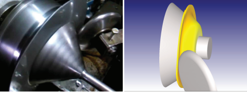
The features and capabilities available in DEFORM V11.1 now make it practical to simulate a variety of spinning applications. An example of a shear spinning operation is shown below (left). Thickness reduction is controlled by the clearance between the roller and the mandrel. The simulation result from a similar case is shown on the right.
Models can be set up and run in a reasonable timeframe with good accuracy. 3D workpiece, mandrel, tailstock, headstock and roll geometries may be generated from 2D crosssections. Powerful solvers and mesh controls are applied to the finite-element solution. CNC-controlled roll movement can be defined using advanced path movement controls. A series of passes may be set up using path tables or multiple operations. Solutions may be isothermal or non-isothermal. The entire setup takes place in the exceptionally easy-touse Multiple Operations (MO) interface.
Predictions include shape, defects (laps, pile-up, etc.), strain, temperature, load, torque and roll stress. Simulation allows users to evaluate the influence of blank shape, material, roll/mandrel geometry, feed rate, rotation speed and roller path.
Wheel rims are commonly spun to shape using a flowforming process. This operation reduces the need for machining and improves material yield. The example shown below was provided by The University of Brescia. They simulated the rim spinning process of an aluminum wheel manufacturer. A forged preform was spun to the final rim dimensions using a single roller and multiple passes. Note that it was not necessary to model the disc (face) of the wheel. Good correlation was achieved between the predicted and actual rim cross-sections.

Exciting metal spinning results have been achieved thanks to the ‘state of the art’ simulation capabilities found in DEFORM. SFTC will continue to improve these capabilities based on user feedback. Please contact your local DEFORM distributor for information or assistance.
DEFORM V11.1 Release
DEFORM V11.1 was released in May.
The extensive list of enhancements and
new features include:
Graphical User Interface
• Enhanced multiple operations system
• Stand-alone FORMING EXPRESS
• Preprocessor updates
• Postprocessor improvements
• New Shape Rolling Module
• New Inverse HTC Module
• DOE/optimization enhancements
• Updated Material Suite
• Database viewer
3D FEM
• Extensive 64-bit support
• Dual mesh solver
• Domain decomposition solver
• Enhanced rotational symmetry
• Improved mesh generation
• Solidification and melt modeling
• Induction heating windows
• Carbon content-based CTE
• Resistance functions
• Strain rate filtering
• Combined iso-kinematic hardening
• Improved micro-scale RVE models
• Explicit solver enhancements
• Better air/oil trap convergence
• Upgraded contact search options
2D FEM
• 64-bit solver
• ALE continuous casting
• Solidification and melt modeling
• Combined iso-kinematic hardening
• Improved contact area stopping
• Constant tau friction for torsion
• Direction-dependent CTE
Material Library
• 15 new copper materials added
• 2 new stainless steels added
• 2 new steels added
A complete list of the new features can
be found in the V11.1 release notes
located in the DEFORM User Area.
For further information on DEFORM software, training and consultancy services please contact us.
Read the full newsletter by clicking on ‘Download’:
For full article, view DEFORM Summer 2016